The production of caustic soda (NaOH) and chlorine (Cl2) is one of the world's most important industries. The applications of these chemicals are so diverse that hardly a consumer product is produced that is not dependent, at some stage in its manufacture, on chlorine and alkalies. These products are sold almost entirely to industry for the production of pulp and paper, soaps and detergents, fibers and plastics, petrochemicals, fertilizers, solvents, disinfection chemicals and others.
Process Description
Chemistry
The basic reaction in the Chlorine-Caustic process is as follows:
NaOH + ½H2 + ½Cl2
-->
Below is a brief description of the membrane cell process which is separated
into five primary areas; Brine System, Electrolysis System (cell), Chlorine
Liquefaction, Caustic Evaporation and Hydrochloric Acid Synthesis.
Brine System
Electrolysis System (membrane cells)
A two-stage process is used to attain ultra-pure brine, almost entirely
independent of salt quality. The first stage involves conventional treatment
with caustic soda, and carbonate. In the second stage, ion exchange
treatment, which uses a resin with a very high affinity to multivalent
cations, is utilized. From the ion exchange the pure brine is stored in a
tank(s) and is available for feed to the membrane cells.
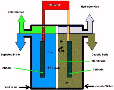
Brine is fed to the anolyte compartment of the cell, and water is fed through
diluted caustic soda to the catholyte compartment. When DC current is
applied to the cell, the ion selective membrane passes mainly positive
sodium ions from the brine to the catholyte compartment. The chloride
ions from the brine are oxidized to chlorine gas at the anode, while
hydrogen and hydroxide ions are formed at the cathode. The membrane
is highly efficient in separating the chlorine and the chloride from the
hydrogen and caustic soda produced.
A significant property of the membrane is the current efficiency (the higher
the current efficiency, the lower the hydroxide leakage through the
membrane). Hydroxide passing through the membrane into the anolyte
compartment leads to the formation of oxygen and hypochlorite. The most
efficient membranes offer a current efficiency of approximately 96% when
producing 31-35% caustic soda.
The chlorine and hydrogen produced in the electrochemical membrane process leave the cells at a pressure slightly higher than atmospheric pressure. After cooling in heat exchangers, the gases can undergo additional processing in the form of chlorine liquefaction, hydrochloric acid production or hypochlorite production.
Chlorine Liquefaction
The chlorine liquefaction system consists of four sections, namely:
![]() Chlorine Drying is carried out in a multi-stage operation, which places
the wet chlorine in contact with varying strengths of sulfuric acid. The
sulfuric acid is pumped into the packed drying columns in a counter-current
fashion to the chlorine gas flow in order to minimize consumption of acid.
From the drying system, the chlorine gas is piped to the chlorine gas
compressor.
Chlorine Drying is carried out in a multi-stage operation, which places
the wet chlorine in contact with varying strengths of sulfuric acid. The
sulfuric acid is pumped into the packed drying columns in a counter-current
fashion to the chlorine gas flow in order to minimize consumption of acid.
From the drying system, the chlorine gas is piped to the chlorine gas
compressor.
![]() Chlorine Compression, the chlorine gas pressure is increased to a
suitable level for the downstream liquefaction unit. The dry compressed
gas is passed through a high efficiency demister for removal of all
entrained acid before entering the chlorine condenser.
Chlorine Compression, the chlorine gas pressure is increased to a
suitable level for the downstream liquefaction unit. The dry compressed
gas is passed through a high efficiency demister for removal of all
entrained acid before entering the chlorine condenser.
![]() Chlorine Liquefaction takes place in a chlorine liquefier that is a
horizontal shell and tube heat exchanger where the chlorine gas is cooled
and condenses to a liquid inside the exchanger tubes. This cooling is
performed by means of a closed-loop compressor based refrigeration system.
Chlorine Liquefaction takes place in a chlorine liquefier that is a
horizontal shell and tube heat exchanger where the chlorine gas is cooled
and condenses to a liquid inside the exchanger tubes. This cooling is
performed by means of a closed-loop compressor based refrigeration system.
![]() Liquid Chlorine Storage - The liquid chlorine then flows by gravity from
the condenser to the liquid chlorine receiving tanks. The condensation
efficiency is dependent on the amount of inert gases in the system, but
typically around 97% is achieved.
Liquid Chlorine Storage - The liquid chlorine then flows by gravity from
the condenser to the liquid chlorine receiving tanks. The condensation
efficiency is dependent on the amount of inert gases in the system, but
typically around 97% is achieved.
Caustic Evaporation
If required, the caustic may be concentrated up to 50% (normal trade quality)
in a caustic evaporation system, which typically could be a single or double
effect falling film evaporator. The 50% caustic could then be further
concentrated and solidified (e.g. flakes).
Hydrochloric Acid Synthesis
If desired, Hydrochloric Acid (HCl) can be produced from the H2 and Cl2
gases in a hydrochloric acid synthesis unit. The HCl synthesis reactor includes the burner tube assembly, the combustion chamber, the hydrochloric acid absorber and tailgas scrubber. Hydrogen gas is supplied from the main hydrogen header from the electrolysis system and chlorine gas from the main chlorine header.
H2 and Cl2 gases enter the combustion chamber and react according to the following highly exothermic reaction to produce hydrogen chloride gas.
H2 + Cl2 ----------> 2 HCl
Cooling water is essential in order to remove the reaction heat.
Hydrochloric acid is produced by absorbing HCl gas in process water.
The water is introduced in the top of the tailgas scrubber and flows
countercurrent to the HCl gas through the absorber down to the HCl
pump tank. From the HCl pump tank the 32-35% hydrochloric acid is
pumped to the HCl storage tanks.